2D-3D Correspondences-based Model Construction
Introduction
Given a 3D Model for a box, we want to re-construct the model from multiple images that captures the model from different angles. First, we build a list of 2D-3D correspondances per image. After that, we estimate the camera pose per image. Then, we project the 2D point onto the 3D model from each image (using the estimated camera pose) to re-construct the 3D model. Eventually, we shall use the constructed models to detect the object in variant poses and occlusions in different images using SIFT-based feature matching.
Note that this is a graduate class project conducted in the ‘‘Tracking and Detection in Computer Vision’’ class in the Technical University of Munich (TUM) taught by Dr. Slobodan Ilic.
Background
During this tutorial, I would assume a basic knowledge of Camera Intrinsics, Exterinsics, World Camera Pose, Point-n-Perspective (PnP) Pose Estimation and Randomly Sampled Consensus (RANSAC). In this section, I will briefly touch on each one of these methods to get you through this tutorial.
Camera Model
For any given point (in the real world), we need to reflect that point in the camera’s perspective, as a point , where:
is the point translated (i.e. shifted) and rotated from the camera’s perspective. is the actual point in real world. is a matrix that represents the ‘‘rotation’’. is a vector that represents the ‘‘translation’’ (i.e. shift).
The above expression could be written in Homogenous coordinates as follows:
where is a rotation and translation matrix. That above operation is now a linear transformation rather than an affine (geometrical) one.
In order to project the 3D $\mathbf M_\text{cam}$ coordinates onto the image plane, we obtain where
We could rewrite that as:
In order to move from a plane projection to an image coordinate system ( and ), we need to know the ratio of pixels per square unit of measurements along each axis ().
Let be the pixels per square unit of measurements along the X- and Y-axis, and be the projection of the camera center in the image coordinate system.
We could squeeze all translation (), rotation () and calibration () into a projection matrix ().
Point-n-Perspective Algorithm (PnP)
The wikipedia explanation of the PnP algorithm is fairly simple to follow. You can also refer to Prof. Prof Steven LaValle lecture on the same topic for a better understanding.
Random Sample Consensus (RANSAC)
RANSAC is an outlier-extraction method that could be used with various regression methods. It defines the quality of regression based on the number of inliers. Inliers/Outliers are defined by comparing distances against a pre-defined threshold. More details are explained in RANSAC Wikipedia article.
Camera Pose Estimation
We used Matlab to manually create the 2D-3D Correspondences between at least 6 points in the image and the box. Those points were usually the corners of the box. After that, we evaluated the camera pose on each image using the following Matlab code:
function [pose] = cameraPose(m, M, maxError)
    % Find tht camera pose given a list of 2d-3d point correspondences
    % m --> Nx2 Image Points
    % M --> Nx3 World Points

    % Camera Intrinsics
    fx = 2960.37845;
    fy = 2960.37845;
    cx = 1841.68855;
    cy = 1235.23369;


    focalLength = [fx fy];
    principalPoint = [cx cy];
    imageSize = [2456 3680];

    intrinsics = cameraIntrinsics(focalLength,principalPoint,imageSize);

    imagePoints = double(m);
    worldPoints = double(M);

    [worldOrientation, worldLocation] = estimateWorldCameraPose(imagePoints,worldPoints,intrinsics,'MaxReprojectionError', maxError);
    [rotationMatrix, translationVector] = cameraPoseToExtrinsics(worldOrientation, worldLocation);

    intrinsicsMatrix = [fx 0 cx; 0 fy cy; 0 0 1];

    pose = struct(...
        'worldOrientation', worldOrientation,...
        'worldLocation', worldLocation,...
        'intrinsicsMatrix', intrinsicsMatrix,...
        'cameraIntrinsics', intrinsics,...
        'rotationMatrix', rotationMatrix,...
        'translationVector', translationVector...
    );
end
SIFT Feature Extraction
I used the vl_feat [1] implementation on Matlab to extract the SIFT features as follows:
% Apply SIFT Feature Extractor
img = imread(img_path);
img_gray = single(rgb2gray(img));
[f,d] = vl_sift(img_gray);

f = transpose(f);
d = transpose(d);

% Project Features On 3D Model
[siftFeatures, ia, ic] = unique(round(f(:, 1:2)), 'rows');
f = f(ia, :);
d = d(ia, :);
3D Model Construction
In order to project the 2D points onto the 3D model, we need the following steps:
- Project given 2D Points in 3D given camera pose and shoot a ray from the center of the camera passing through the projected 3D point.
- Intersect the shoot ray with each face of the box and select the face the meets the following criteria:
- The ray intersects the plane in which the face lies.
- The plane faces the camera; at any point, there are two faces with which our ray will intersect: one on the side of the box that faces the camera and the other on the back of the box– thus, not facing the camera.
- The intersection point should lie on that face (and, thus on the box) not just on the plane.
A face is defined as a triangle here. And, the box has 12 triangles (2 lying on each side of the box– a box has 6 sides, right?).
Step 1: Shoot Ray
In order to project the 2D points in the world coordinates (i.e. in 3D), we need the projection matrix. In order to get the projection matrix, we need the calibration matrix, rotation matrix, and translation vector. Calibration matrix is priori. Rotation matrix and translation vector are obtained from the estimated pose. Another workaround is to use the worldOrientation and worldLocation given by the estimateWorldCameraPose matlab function to evaluate the 3D point directly through the following equation:
where is the world orientation, and is the world location.
function [ray] = shootRay(point, pose)

    mTelda = [point 1]';  % 3x1 Image Point

    projection = inv(pose.worldOrientation) * inv(pose.intrinsicsMatrix) * mTelda + transpose(pose.worldLocation);
    % projection = projection(1:3) / projection(4)
    P2 = transpose(projection);
    P1 = pose.worldLocation;  % This is the camera's location
    l = P2 - P1;

    ray = struct( ...
        'p1', P1, ...
        'p2', P2, ...
        'l', l ...
    );
end
Step 2: Find Ray-Face/Triangle Intersection Point
Sub-Step 2.1: Intersect Ray with Plane of Triangle/Face
Here, I am using the Plane Line Intersection Matlab code by Nassim Khaled to check for intersection and get the intersection point.
% Now, we get the vectors between the three triangle faces
v1 = face.p2 - face.p1;
v2 = face.p2 - face.p3;

% Now, we get the norm (orthogonal to the surface) of that triangle/face
n = cross(v1, v2);

% Now, we check for intersection :-)
[point, check]=plane_line_intersect(n, face.p1', ray.p1', ray.p2');  % V0 = p1 or p2 or p3 (doesn't matter!)
Sub-Step 2.2: Choose Plane Intersection That Faces The Camera
We could do that by checking if the angle between the norm of the plane and the intersection ray is less than 90 degrees as follows:
% If there is an intersection, check the angle to make sure we are looking at the correct (camera-facing) triangle!
ThetaInDegrees = atan2d(norm(cross(n,ray.l)),dot(n,ray.l));
facingTheCamera = ThetaInDegrees < 90;
Sub-Step 2.3: Intersection Point Should Lie on that Triangle/Face
Given that the point lies in the same plane as the triangle, a simple check that the area of the triangle is equal to the sum of all sub-triangles created by the new point on the triangle should do the trick. Formally, assume that a triangles has three points , and , and the intersection point is . The following equality should hold:
if facingTheCamera
    sumOfAreas = ...
        triangleArea(point, face.p1, face.p2) + ...
        triangleArea(point, face.p2, face.p3) + ...
        triangleArea(point, face.p3, face.p1);
    faceArea = triangleArea(face.p1, face.p2, face.p3);
    onTheTriangle = isequalfp(sumOfAreas, faceArea); % floating point equality
else
    onTheTriangle = false;
end
Step 3: Put it all together!
function [intersection] = rayIntersectsFace(ray, face)
    % Input:
    % face = struct({ p1, p2, p3 })
    % ray = struct({ p0, p1, l })

    % Now, we get the vectors between the three triangle faces
    v1 = face.p2 - face.p1;
    v2 = face.p2 - face.p3;

    % Now, we get the norm (orthogonal to the surface) of that triangle/face
    n = cross(v1, v2);

    % Now, we check for intersection :-)
    [point, check]=plane_line_intersect(n, face.p1', ray.p1', ray.p2');  % V0 = p1 or p2 or p3 (doesn't matter!)
    point = transpose(point);

    % If there is an intersection, check the angle to make sure we are looking at the correct (camera-facing) triangle!
    ThetaInDegrees = atan2d(norm(cross(n,ray.l)),dot(n,ray.l));
    facingTheCamera = ThetaInDegrees < 90;

    if facingTheCamera
        sumOfAreas = ...
            triangleArea(point, face.p1, face.p2) + ...
            triangleArea(point, face.p2, face.p3) + ...
            triangleArea(point, face.p3, face.p1);
        faceArea = triangleArea(face.p1, face.p2, face.p3);
        onTheTriangle = isequalfp(sumOfAreas, faceArea); % floating point equality
    else
        onTheTriangle = false;
    end

    intersection = struct(...
        'theta', ThetaInDegrees, ...
        'onThePlane', check, ...
        'point', point, ...
        'facingTheCamera', facingTheCamera,...
        'onTheTriangle', onTheTriangle...
    );
end
Final Pipeline: 3D Model Construction
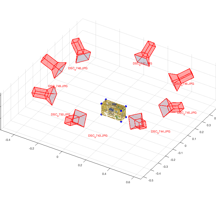
Now, we have all components to loop through all of the images (here, those are 8 images) and reconstruct the model.
[FACES] = getFaces();  % a list of all 12 triangles of the box
features = containers.Map;

for i = 1:8
    key = strcat('image_', num2str(42+i),'.jpg');
    % Manually-picked correspondences
    pairs = correspondences(key);
    err = errors(key);

    points = [];
    colors = [];
    sift_f = [];
    sift_d = [];
    box_sides = [];

    fprintf('Processing %s ...\n', key);

    % Estimate The Camera's Real World Pose
    [pose] = cameraPose(pairs.m, pairs.M, err);

    % Apply SIFT Feature Extractor
    img_path = strcat('~/Downloads/data/images/init_texture/', key);
    img = imread(img_path);
    img_gray = single(rgb2gray(img));
    [f,d] = vl_sift(img_gray);

    f = transpose(f);
    d = transpose(d);

    % Project Features On 3D Model
    [siftFeatures, ia, ic] = unique(round(f(:, 1:2)), 'rows');
    f = f(ia, :);
    d = d(ia, :);

    N = length(f);
    for i = 1:N  % For each SIFT feature
        x = siftFeatures(i, 1);
        y = siftFeatures(i, 2);
        point = [x y];

        % Shoot the ray (i.e. get a ray/line from an image coordinates)
        [ray] = shootRay(point, pose);

        for j = 1:12
            % Form the face
            face = struct( ...
                'p1', cloud.Location(FACES(j, 1), :), ...
                'p2', cloud.Location(FACES(j, 2), :), ...
                'p3', cloud.Location(FACES(j, 3), :) ...
            );

            box_side = FACES(j, 4);

            % Intersect the face with the ray
            [intersection] = rayIntersectsFace(ray, face);


            if intersection.onThePlane & intersection.facingTheCamera & intersection.onTheTriangle
                points = [points; intersection.point];
                colors = [colors; reshape(img(y,x,:), 1, 3)];
                sift_f = [sift_f; f(i, :)];
                sift_d = [sift_d; d(i, :)];
                box_sides = [box_sides; box_side];

                % Given we found the right traingle (to which the 2d feature belong), we stop looking.
                break
            end
        end
    end

    features(key) = struct(...
        'points', points,...
        'colors', colors,...
        'box_sides', box_sides,...
        'f', sift_f, 'd', sift_d...
    );
end
Now, we plot the camera world locations and the box with the SIFT-features on it. However, we don’t plot the sift features themselves, we plot RGB values instead.
3D Model Constructed from 8 Images from Different Camera Poses
References
- [1]A. Vedaldi and B. Fulkerson, “VLFeat: An Open and Portable Library of Computer Vision Algorithms.” 2008 [Online]. Available at: http://www.vlfeat.org/